

HF83111_VC1/HF83111Q_VC1
Dual-Mode PCM 768KHz/DSD512 USB HiFi Decoder with USB(UAC2.0/UAC1.0) Input and I²S(Master) Output
1. Introduction
1.1 Product Description
The HF83111_VC1/HF83111Q_VC1 is a dual-mode USB-I²S HiFi audio decoder supporting up to PCM 768KHz/DSD512, specifically designed for HiFi decoder audio applications.
The HF83111_VC1/HF83111Q_VC1 supports USB Audio Class 1.0/2.0 and I²S interfaces. The flexible audio interface allows the HF83111_VC1/HF83111Q_VC1 to connect to various audio data converters, digital audio receivers and transmitters, and digital signal processors.
The HF83111_VC1/HF83111Q_VC1 provides two input/output modes: USB(UAC2.0) input/I²S(Master) output (default at power-on) and USB(UAC1.0) input/I²S(Master) output, meeting the requirements of different application scenarios.
Important Notice
The HF83111Q_VC1 model supports MQA audio decoding, while the HF83111_VC1 model does not support this feature.
1.2 Product Features
Audio Performance Features
- Supports input and output sampling rates up to 768kHz
- Supports DSD64/128/256/512 formats
- HF83111Q_VC1 supports MQA decoding
- Built-in SSRC and ASRC modules, supporting conversion between different interfaces and different sampling rates
- Supports 16-32bit audio data formats
Interface Support Features
- Multiple digital interface support
- Supports USB audio input
- Supports I²S master mode audio output
- Supports UART configuration interface
USB Functionality Features
- USB interface features
- Supports UAC 1.0
- Supports UAC 2.0
- Supports firmware upgrade via USB
- Supports HID, MCU firmware can be upgraded via HID
System Compatibility - UAC 2.0 protocol, supports ASIO - Supports multiple operating systems such as Windows, Linux, Android, macOS, and iOS
1.3 Application Scenarios
- USB HiFi Decoder
- USB HiFi Audio Interface
- USB HiFi Digital Player
1.4 Product Functional Block Diagram
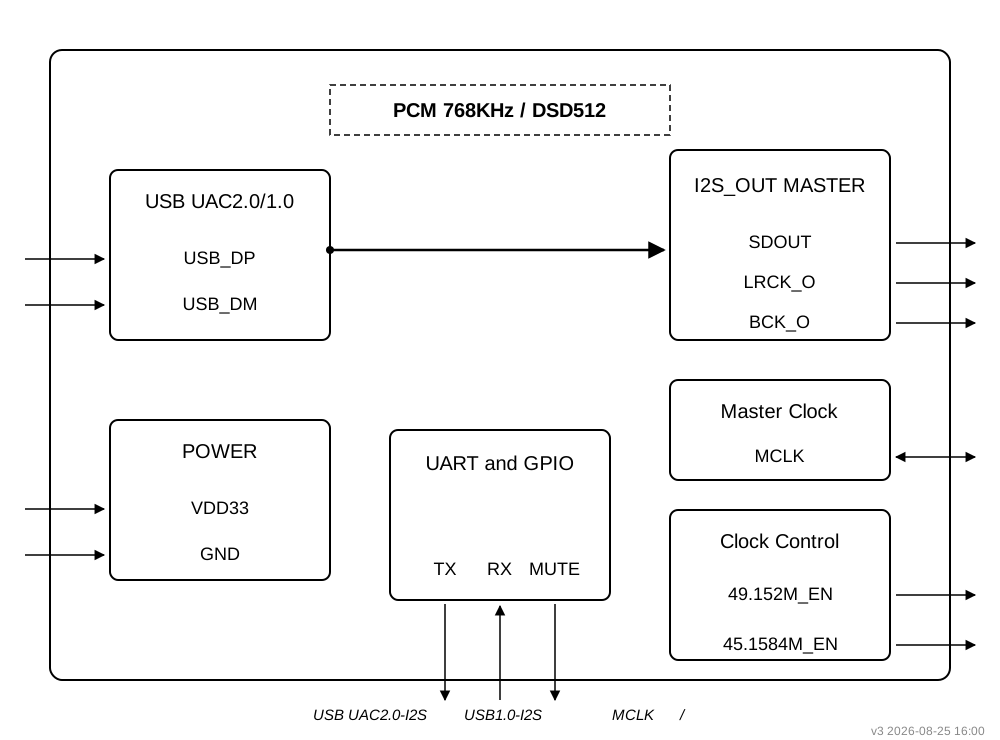
1.5 Ordering Information
| PRODUCT | ORDERING NUMBER | PACKAGE BODY | SIZE (NOM) | Hardware Model | Comments |
|---|---|---|---|---|---|
| HF83111_VC1 | HF83111-VC1 | SMT LGA-52 | 13x13mm | A316-Mini-V1 | |
| HF83111Q_VC1 | HF83111Q-VC1 | SMT LGA-52 | 13x13mm | A316-Mini-V1 | Supports MQA Decoding |
2. Modes and Specifications
2.1 Supported Input/Output Modes
| Mode Number | Input/Output Mode | Description | Mode Switching Command Value (Refer to Product Configuration Protocol Commands 0x03 and 0x23) |
|---|---|---|---|
| 1 | USB(UAC2.0) in-I²S(Master) out | USB input, I²S output, UAC2.0, default at power-on | 0x00, 0x80, 0xa9, 0x00, 0x01 |
| 2 | USB(UAC1.0) in-I²S(Master) out | USB input, I²S output, UAC1.0 | 0x00, 0x80, 0x01, 0x00, 0x02 |
2.2 Detailed Parameters for Each Operating Mode
2.2.1 USB(UAC2.0) in → I²S out Mode
Supported Audio Formats and Sampling Rates:
| Audio Format | Supported Sampling Rates |
|---|---|
| PCM | 44.1kHz, 48kHz, 88.2kHz, 96kHz, 176.4kHz, 192kHz, 352.8kHz, 384kHz, 705.6kHz, 768KHz |
| DSD Native | DSD64, DSD128, DSD256, DSD512 |
| DOP | DOP64, DOP128, DOP256 |
| MQA | HF83111Q_VC1 only |
2.2.2 USB(UAC1.0) in → I²S out Mode
Supported Audio Formats and Sampling Rates:
| Audio Format | Supported Sampling Rates |
|---|---|
| PCM | 48kHz |
3. Pin Configuration and Functions
3.1 HF83111_VC1/HF83111Q_VC1 Pin Layout

3.2 HF83111_VC1/HF83111Q_VC1 Pin Description
| Pin Number | Name | Type | Function |
|---|---|---|---|
| 1 | 3.3V | P | Module 3.3V power supply |
| 2 | X1D13 | I/O | NC |
| 3 | X1D16 | I/O | NC |
| 4 | GND | P | Module ground |
| 5 | X1D17 | I/O | NC |
| 6 | X1D18 | I/O | NC |
| 7 | X1D19 | I/O | NC |
| 8 | X1D22 | I/O | NC |
| 9 | X0D29 | I/O | NC |
| 10 | X0D35 | I/O | I²S_OUT_BCLK(MASTER) |
| 11 | X0D36 | I/O | I²S_OUT_LRCLK(MASTER) |
| 12 | X0D37 | I/O | NC |
| 13 | X0D38 | I/O | I²S_OUT_DATA0(MASTER) |
| 14 | X0D40 | I/O | NC |
| 15 | X0D39 | I/O | I²S_OUT_MCLK(MASTER) |
| 16 | X0D42 | I/O | NC |
| 17 | X0D41 | I/O | NC |
| 18 | X0D43 | I/O | NC |
| 19 | X1D34 | I/O | NC |
| 20 | GND | P | Module ground |
| 21 | X0D30 | I/O | CTL_MUTE; control output, active low |
| 22 | X0D31 | I/O | NC |
| 23 | X0D32 | I/O | 49.152 MHz clock control |
| 24 | X0D33 | I/O | 45.1584 MHz clock control |
| 25 | GND | P | Module ground |
| 26 | GND | P | Module ground |
| 27 | GND | P | Module ground |
| 28 | X0D00 | I/O | UART_TX, connect to MCU_RX |
| 29 | X0D11 | I/O | UART_RX, connect to MCU_TX |
| 30 | X1D00 | I/O | NC |
| 31 | X1D01 | I/O | NC |
| 32 | GND | P | Module ground |
| 33 | X1D09 | I/O | NC |
| 34 | X1D10 | I/O | NC |
| 35 | X1D11 | I/O | Connect to Pin 15 X0D39 |
| 36 | GND | P | Module ground |
| 37 | GND | P | Module ground |
| 38 | TDI | I/O | XTAG debug pin |
| 39 | TDO | I/O | XTAG debug pin |
| 40 | TMS | I/O | XTAG debug pin |
| 41 | TCK | I/O | XTAG debug pin |
| 42 | RST_N | I/O | System reset, active low |
| 43 | 1.8V | P | Module 1.8V power supply |
| 44 | GND | P | Module ground |
| 45 | USB_DM | I/O | USB_DM |
| 46 | USB_DP | I/O | USB_DP |
| 47 | GND | P | Module ground |
| 48 | 0.9V | P | Module 0.9V power supply |
| 49 | GND | P | Module ground |
| 50 | GND | P | Module ground |
| 51 | GND | P | Module ground |
| 52 | GND | P | Module ground |
Pin Type Description
I/O type definitions in the table: I=Input, O=Output, P=Power, I/O=Input/Output
4. Hardware Specifications
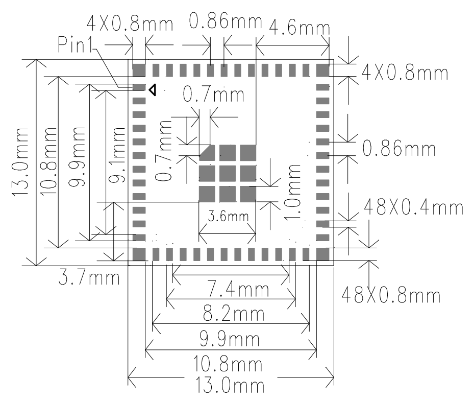
4.1 Product Dimensions
13±0.1mm(L)X13±0.1mm(W)X0.8±0.1mm(H)
4.2 Module Package Diagram
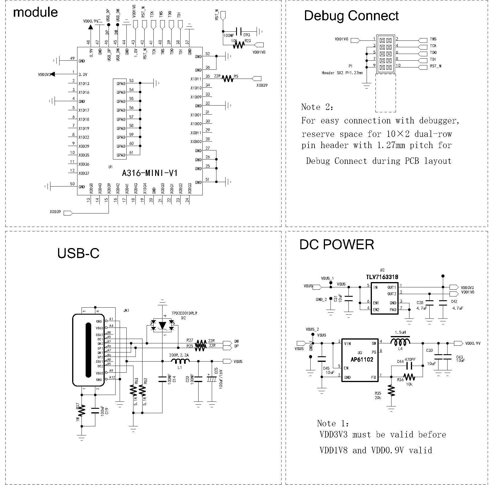
5. Minimum System Reference Design
6. Product Packaging Information
Tray + Outer Box Packaging
7. Revision History
| Version | Date | Description | Revised By |
|---|---|---|---|
| V1.0 | 2026-08-25 | Initial release | |