

AH86G11-VC1
16-in/16-out TDM256 Slave 48kHz / 24bit·32bit USB Multi-channel Digital Audio Interface
1. Introduction
1.1 Product Description
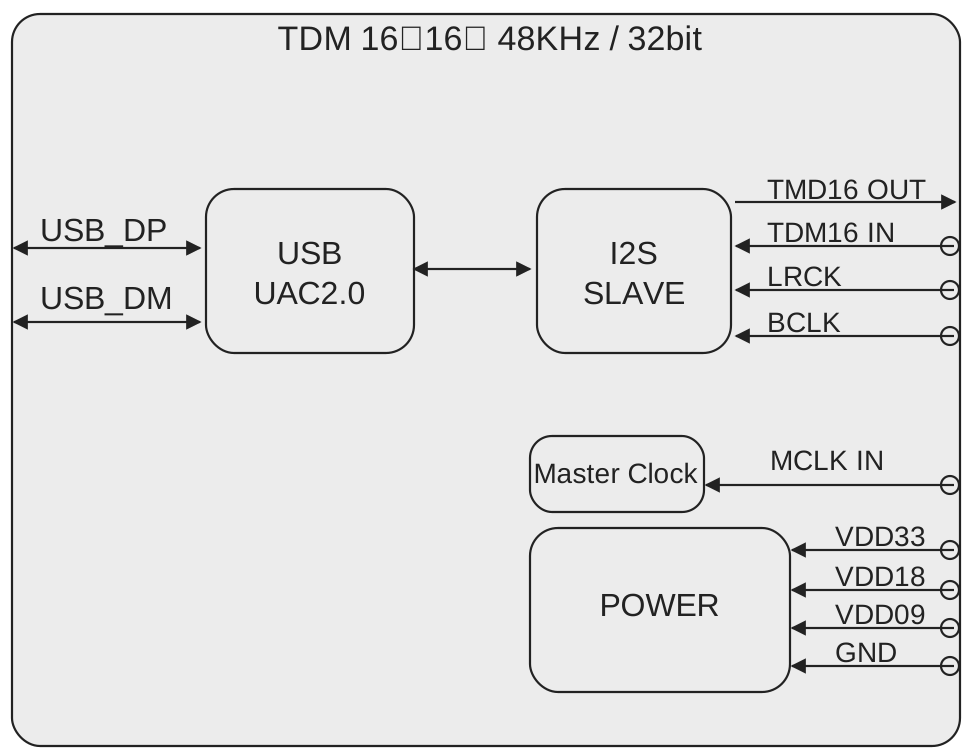
AH86G11 is a USB multi-channel digital audio interface core module based on the xcore.ai (XMOS) multi-core architecture, designed for audio front-end applications that interconnect with an external DSP in digital mixing consoles / multi-channel mixing systems. AH86G11 connects to a host (PC / Mac) via a USB Audio Interface (UAC), and externally provides a 16-channel input / 16-channel output TDM digital audio interface to interconnect with a DSP. It adopts the TDM256 frame format (8 channels per data line), implementing 16-in / 16-out through 2 input data lines and 2 output data lines.
AH86G11 operates in Slave mode with a fixed sampling rate of 48kHz, and supports 24bit / 32bit audio data bit depths: USB supports 48K 24bit/32bit, while TDM supports only 32bit. The clock is provided by the external DSP: the DSP outputs the bit clock BCLK (I2S0_SCLK) and the frame sync FS (I2S0_LRCLK) to AH86G11, and AH86G11 operates as a clock slave.
1.2 Product Features
Audio Interface Features
- USB Audio Interface (UAC): Multi-channel USB audio interface connecting to a host (PC / Mac), 48kHz / 24bit·32bit
- TDM256 Multi-channel Interface: 16-in / 16-out, 2 TDM256 input data lines (16 channels) + 2 TDM256 output data lines (16 channels), 8 channels per data line
- Sampling Rate: Fixed 48kHz
- Bit Depth: USB supports 24bit / 32bit; TDM supports only 32bit
Clock Features
- Slave Mode: The clock is provided by the external DSP; the DSP outputs the bit clock
BCLK(I2S0_SCLK) and the frame syncFS(I2S0_LRCLK), and AH86G11 operates as a clock slave - Only 2 external clock lines:
BCLK+FS MCLK: The DSP may not provide it separately; if not provided, the user may connect MCLK to BCLK (MCLK = BCLK)
1.3 Application Scenarios
- Digital Mixer — multi-channel audio front-end for mixing consoles, forms a mixing / effects processing chain with an external DSP, 16-in / 16-out channel routing
- Multichannel Audio Router — channel-level digital audio distribution, TDM multi-channel interconnection, signal aggregation for recording / PA systems
- Conference / PA System — multi-microphone channel aggregation, audio interface interfacing with the system DSP, fixed 48kHz engineering audio applications
1.4 Product Functional Block Diagram
1.5 Ordering Information
| PRODUCT MODEL | ORDERING NUMBER | PACKAGE BODY | SIZE (NOM) | Hardware Model | Comments |
|---|---|---|---|---|---|
| AH86G11-VC1 | AH86G11-VC1 | SMT LGA-52 | 13×13mm | A316-Mini-V1 | 16-in/16-out TDM256 USB multi-channel digital audio interface core module, 48kHz / 24bit·32bit |
2. Modes and Specifications
2.1 Supported Input and Output Modes
| Mode Number | Input/Output Mode | Description |
|---|---|---|
| 1 | TDM256(Slave) in - USB out / USB in - TDM256(Slave) out | TDM256 input (DSP) / USB output (16 channels) / USB input (16 channels) / TDM256 output (DSP) |
2.2 Detailed Parameters for Each Operating Mode
2.2.1 USB Audio Mode
Audio Format and Sampling Rate:
| Audio Format | Specification |
|---|---|
| USB Audio | USB Audio Class (UAC), multi-channel |
| Sampling Rate | 48kHz (fixed) |
| Bit Depth | 24bit / 32bit |
2.2.2 TDM256 Slave Mode
Audio Format and Sampling Rate:
| Audio Format | Specification |
|---|---|
| PCM / TDM | TDM256, 8 channels per data line |
| Sampling Rate | 48kHz (fixed) |
| Bit Depth | 32bit |
| Input Channels | 16 (2 × TDM256 input lines) |
| Output Channels | 16 (2 × TDM256 output lines) |
3. Pin Configuration and Functions
3.1 Module Pin Layout

3.2 Module Pin Description
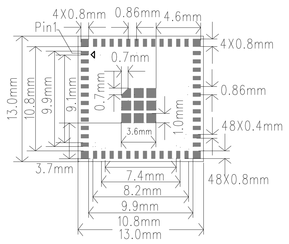
The module uses the A316-Mini-V1 (SMT LGA-52, 13×13mm) package. The physical mapping of the 52 external LGA pads to the XMOS pins is as follows:
| Pin Number | Name | Type | Function |
|---|---|---|---|
| 1 | 3.3V | P | Module 3.3V Power Supply |
| 2 | X1D13 | - | NC |
| 3 | X1D16 | - | NC |
| 4 | GND | P | Module Ground |
| 5 | X1D17 | - | NC |
| 6 | X1D18 | - | NC |
| 7 | X1D19 | - | NC |
| 8 | X1D22 | - | NC |
| 9 | X0D29 | - | NC |
| 10 | X0D35 | I (Slave) | I2S0_SCLK / BCLK |
| 11 | X0D36 | I (Slave) | I2S0_LRCLK / FS |
| 12 | X0D37 | O | I2S0_OUT1 |
| 13 | X0D38 | O | I2S0_OUT0 |
| 14 | X0D40 | - | NC |
| 15 | X0D39 | O | MCLK |
| 16 | X0D42 | - | NC |
| 17 | X0D41 | - | NC |
| 18 | X0D43 | - | NC |
| 19 | X1D34 | - | NC |
| 20 | GND | P | Module Ground |
| 21 | X0D30 | O | CTL_MUTE |
| 22 | X0D31 | - | NC |
| 23 | X0D32 | - | NC |
| 24 | X0D33 | - | NC |
| 25 | GND | P | Module Ground |
| 26 | GND | P | Module Ground |
| 27 | GND | P | Module Ground |
| 28 | X0D00 | I | I2S0_IN0 |
| 29 | X0D11 | I | I2S0_IN1 |
| 30 | X1D00 | - | NC |
| 31 | X1D01 | - | NC |
| 32 | GND | P | Module Ground |
| 33 | X1D09 | - | NC |
| 34 | X1D10 | - | NC |
| 35 | X1D11 | O | MCLK, connect to Pin 15 X0D39 |
| 36 | GND | P | Module Ground |
| 37 | GND | P | Module Ground |
| 38 | TDI | I/O | JTAG / XTAG Debug PIN |
| 39 | TDO | I/O | JTAG / XTAG Debug PIN |
| 40 | TMS | I/O | JTAG / XTAG Debug PIN |
| 41 | TCK | I/O | JTAG / XTAG Debug PIN |
| 42 | RST_N | I | System reset, active low |
| 43 | 1.8V | P | Module 1.8V Power Supply |
| 44 | GND | P | Module Ground |
| 45 | USB_DM | I/O | USB_DM |
| 46 | USB_DP | I/O | USB_DP |
| 47 | GND | P | Module Ground |
| 48 | 0.9V | P | Module 0.9V Power Supply |
| 49 | GND | P | Module Ground |
| 50 | GND | P | Module Ground |
| 51 | GND | P | Module Ground |
| 52 | GND | P | Module Ground |
4. Hardware Specifications
4.1 Product Dimensions
13±0.1mm(L)X13±0.1mm(W)X0.8±0.1mm(H)
4.2 Module Package Diagram
5. Minimum System Reference Design
6. Product Packaging Information
Tray + Outer Box Packaging
7. Revision History
| Version | Date | Description | Revised By |
|---|---|---|---|
| V1.0 | 2026-06-16 | Initial release | Technical Dept. |