XMAU7118-VC1
16-Channel PDM to I²S/TDM Audio Converter with Dual PDM Clock Output and UART/I²C Configuration Interface
1. Overview
1.1 Product Description
XMAU7118 is a professional-grade 16-channel PDM to I²S/TDM audio converter developed based on XMOS high-performance chips, specifically designed for digital microphone array applications. This product supports 16 PDM digital microphone inputs, provides 32-bit audio resolution and exceptional audio performance.
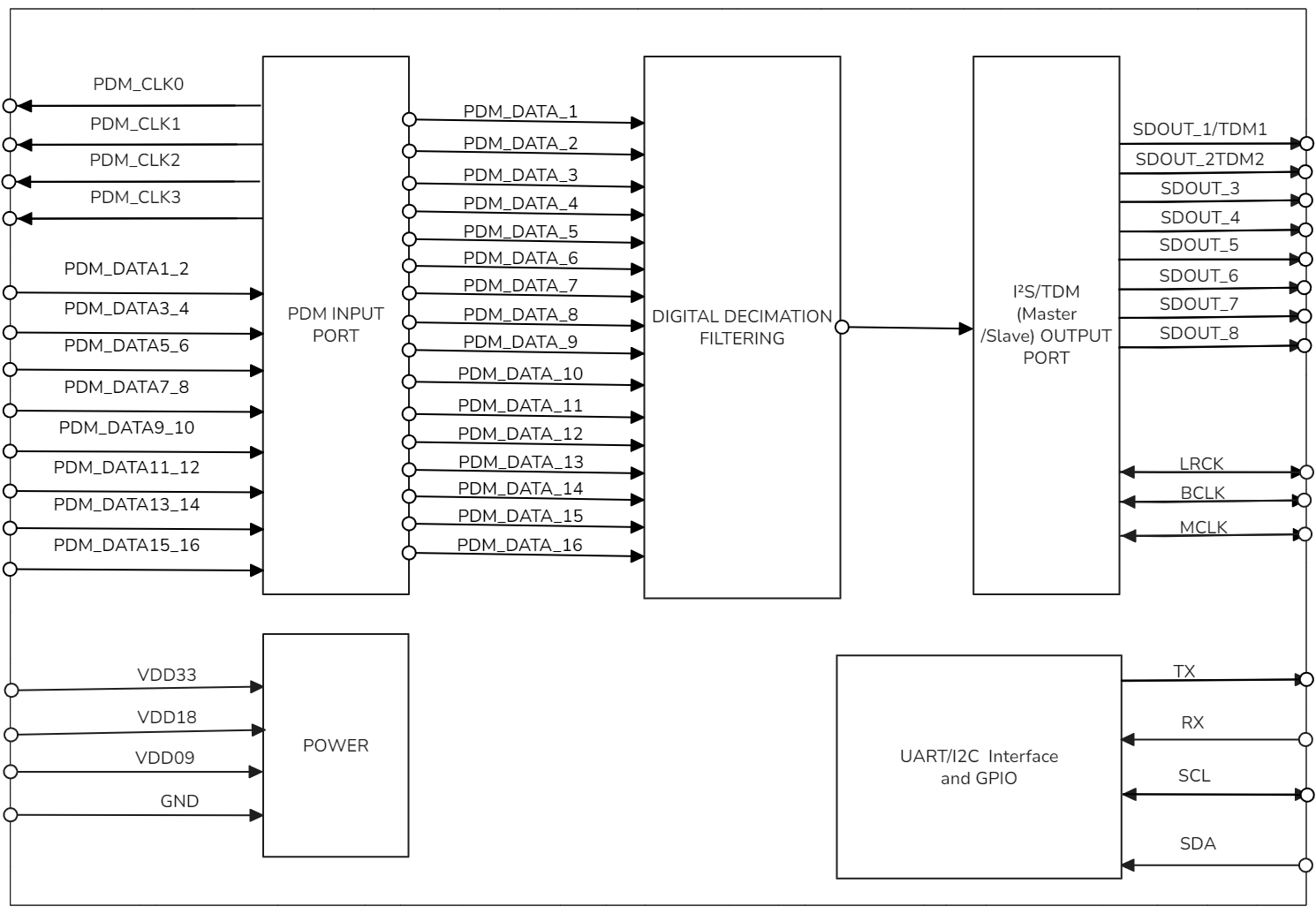
- The product integrates powerful digital signal processing capabilities, supports simultaneous input from 16 PDM microphones, with output sample rates ranging from 4kHz to 192kHz, meeting the requirements of various audio acquisition application scenarios.
- Supports standard I²S and TDM audio output formats, provides 8 independent SDATA output channels, can operate in Master or Slave mode, offering high flexibility for system integration.
- The product features excellent audio performance metrics with THD+N less than -110dB, dynamic range up to 140dB, and complete parameter configuration via UART/I²C interface, providing audio equipment manufacturers with professional-grade multi-channel audio acquisition solutions.
1.2 Product Features
-
Multi-Channel Audio Processing Capability
16-Channel PDM Digital Microphone Input
- Supports simultaneous input from 16 PDM digital microphones
- Provides 32-bit audio resolution processing precision
- Achieves <-110dB THD+N and 140dB dynamic range
Flexible Sampling Rate Configuration
- Output sampling rate covers 4kHz to 192kHz range
- Automatically detects and adapts to different sampling rates
- Supports sampling rate configuration via I²C/UART interface
-
Intelligent Clock Management
Integrated PDM Clock Output Function (PDM_CLK)
- Clock frequency: 3.072MHz (typical)
- Can drive 16 PDM microphones
- Single clock design simplifies routing
Supports Automatic PDM Clock Generation Mechanism
- No external clock source required
- Automatic clock synchronization
-
Standard Audio Output Interface
Supports I²S and TDM Audio Output Formats
- Standard I²S format support
- TDM multi-channel format support
- 8 independent SDATA output channels
Supports Master/Slave Operating Modes
- I²S Master mode
- I²S Slave mode
- TDM Master mode
- TDM Slave mode
-
Flexible Configuration Interface
I²C/UART Configuration Interface
- Select interface type via pin pull-up/pull-down
- Pull-up: UART mode
- Pull-down: I²C mode
Configurable Parameters
- I²S/TDM format switching
- Sampling rate configuration (4kHz~192kHz)
- Master/Slave mode switching
- Dynamic switching between multiple operating modes
1.3 Application Scenarios
-
Smart Speakers and Voice Assistant Systems
- Far-field pickup arrays in smart speakers
- Multi-microphone noise reduction in voice assistant devices
- Voice recognition in smart home control centers
-
Professional Conference and Video Communication Equipment
- Multi-point pickup in video conferencing systems
- Omnidirectional pickup in remote collaboration devices
- Array microphone processing in conference phones
-
Industrial Audio Monitoring and Security Systems
- Multi-point acquisition in industrial equipment acoustic monitoring
- Sound source localization in security systems
- Multi-channel acquisition in environmental noise monitoring
-
Automotive Audio and In-Vehicle Communication Systems
- Microphone arrays in in-vehicle voice recognition systems
- Multi-microphone processing in in-vehicle call noise reduction
- Voice interaction in smart cockpits
1.4 Product Functional Block Diagram

1.5 Ordering Information
| PRODUCT MODEL | ORDERING NUMBER | PACKAGE BODY | SIZE (NOM) | Hardware Model | Comments |
|---|---|---|---|---|---|
| XMAU7118-VC1 | XMAU7118-VC1 | SMT LGA-52 | 13x13mm | A316-Mini-V1 | 16-channel PDM to I²S/TDM audio converter, supports 4kHz~192kHz sampling rate, 8-channel SDATA output |
2. Modes and Specifications
2.1 Supported Input/Output Modes
XMAU7118-VC1 supports 4 operating modes, which can be configured and switched via I²C/UART interface:
| Mode Number | Input/Output Mode | Description |
|---|---|---|
| 1 | 16-Channel PDM In → I²S Master Out (8 SDATA) | 16-channel PDM microphone input, I²S Master mode output, 8 independent SDATA outputs |
| 2 | 16-Channel PDM In → I²S Slave Out (8 SDATA) | 16-channel PDM microphone input, I²S Slave mode output, 8 independent SDATA outputs |
| 3 | 16-Channel PDM In → TDM Master Out | 16-channel PDM microphone input, TDM Master mode output |
| 4 | 16-Channel PDM In → TDM Slave Out | 16-channel PDM microphone input, TDM Slave mode output |
2.2 Detailed Parameters for Each Operating Mode
2.2.1 Mode 1: 16-Channel PDM → I²S Master Output Mode
Input/Output Parameters:
| Parameter | Input | Output |
|---|---|---|
| Interface | PDM (16 channels) | I²S Master (8 SDATA) |
| Audio Format | PDM | PCM |
| Sampling Rate | - | 4kHz~192kHz (configurable) |
| Bit Depth | - | 32bit |
| Channels | 16 | 16 (2 channels per SDATA output) |
PDM Clock Configuration:
- PDM_CLK: 3.072MHz (typical)
- PDM_CLK can connect to 16 PDM microphones
- Single clock design simplifies routing
2.2.2 Mode 2: 16-Channel PDM → I²S Slave Output Mode
Input/Output Parameters:
| Parameter | Input | Output |
|---|---|---|
| Interface | PDM (16 channels) | I²S Slave (8 SDATA) |
| Audio Format | PDM | PCM |
| Sampling Rate | - | 4kHz~192kHz (provided by external master device) |
| Bit Depth | - | 32bit |
| Channels | 16 | 16 (2 channels per SDATA output) |
2.2.3 Mode 3: 16-Channel PDM → TDM Master Output Mode
Input/Output Parameters:
| Parameter | Input | Output |
|---|---|---|
| Interface | PDM (16 channels) | TDM Master |
| Audio Format | PDM | PCM |
| Sampling Rate | - | 4kHz~192kHz (configurable) |
| Bit Depth | - | 32bit |
| Channels | 16 | 16 (TDM time-division multiplexing) |
2.2.4 Mode 4: 16-Channel PDM → TDM Slave Output Mode
Input/Output Parameters:
| Parameter | Input | Output |
|---|---|---|
| Interface | PDM (16 channels) | TDM Slave |
| Audio Format | PDM | PCM |
| Sampling Rate | - | 4kHz~192kHz (provided by external master device) |
| Bit Depth | - | 32bit |
| Channels | 16 | 16 (TDM time-division multiplexing) |
2.3 Audio Performance Specifications
| Performance Specification | Specification | Notes |
|---|---|---|
| THD+N | < -110dB | @1kHz, 0dBFS |
| Dynamic Range | 140dB | A-weighted |
| Audio Resolution | 32bit | - |
| Sampling Rate Range | 4kHz~192kHz | Configurable |
| PDM Input Channels | 16 | - |
| I²S/TDM Output Channels | 16 | - |
2.4 Feature Comparison
| Feature | XMAU7118 | ADAU7118 | Advantage |
|---|---|---|---|
| PDM Input Channels | 16 channels | 8 channels | 2x channel count |
| Audio Sampling Rate and Bit Depth | 4KHz~192KHz/32bit | 4KHz~192KHz/24bit | Higher bit depth |
| Dynamic Range | 140dB | 126dB | 14dB improvement |
| Control Interface | UART+I²C | I²C | More control interfaces |
| I²S Operating Mode | Master/Slave | Slave | More operating modes |
3. Pin Configuration and Functions
3.1 XMAU7118_VC1 Pin Layout

3.2 XMAU7118_VC1 Pin Description
| Pin Number | Name | Type | Function |
|---|---|---|---|
| 1 | 3.3V | P | Module 3.3V power supply |
| 2 | X1D13 | O | TDM_OUT2 (TDM data output 2) |
| 3 | X1D16 | - | Reserved |
| 4 | GND | P | Module ground |
| 5 | X1D17 | - | Reserved |
| 6 | X1D18 | - | Reserved |
| 7 | X1D19 | - | Reserved |
| 8 | X1D22 | I/O | UART_RX/I2C_SDA (UART receive/I2C data) |
| 9 | X0D29 | - | Reserved |
| 10 | X0D35 | O | PDM_CLK (PDM clock output) |
| 11 | X0D36 | I | PDM_DATA1_2 (PDM microphone 1 and 2 data input) |
| 12 | X0D37 | I | PDM_DATA3_4 (PDM microphone 3 and 4 data input) |
| 13 | X0D38 | I | PDM_DATA5_6 (PDM microphone 5 and 6 data input) |
| 14 | X0D40 | I | PDM_DATA9_10 (PDM microphone 9 and 10 data input) |
| 15 | X0D39 | I | PDM_DATA7_8 (PDM microphone 7 and 8 data input) |
| 16 | X0D42 | I | PDM_DATA13_14 (PDM microphone 13 and 14 data input) |
| 17 | X0D41 | I | PDM_DATA11_12 (PDM microphone 11 and 12 data input) |
| 18 | X0D43 | I | PDM_DATA15_16 (PDM microphone 15 and 16 data input) |
| 19 | X1D34 | I/O | UART_TX'/I2C_SCL (UART transmit/I2C clock) |
| 20 | GND | P | Module ground |
| 21 | X0D30 | - | Reserved |
| 22 | X0D31 | - | Reserved |
| 23 | X0D32 | - | Reserved |
| 24 | X0D33 | - | Reserved |
| 25 | GND | P | Module ground |
| 26 | GND | P | Module ground |
| 27 | GND | P | Module ground |
| 28 | X0D00 | - | Reserved |
| 29 | X0D11 | O | MCLK (Master clock output) |
| 30 | X1D00 | O | TDM_LRCK (TDM frame sync) |
| 31 | X1D01 | O | TDM_OUT1 (TDM data output 1) |
| 32 | GND | P | Module ground |
| 33 | X1D09 | I/O | UART_I2C_SEL (UART/I2C selection) |
| 34 | X1D10 | O | TDM_BCLK (TDM bit clock) |
| 35 | X1D11 | O | MCLK (Master clock output) |
| 36 | GND | P | Module ground |
| 37 | GND | P | Module ground |
| 38 | TDI | I/O | XTAG debug pin |
| 39 | TDO | I/O | XTAG debug pin |
| 40 | TMS | I/O | XTAG debug pin |
| 41 | TCK | I/O | XTAG debug pin |
| 42 | RST_N | I | System reset, active low |
| 43 | 1.8V | P | Module 1.8V power supply |
| 44 | GND | P | Module ground |
| 45 | USB_DM | I/O | USB_DM (Reserved, not used) |
| 46 | USB_DP | I/O | USB_DP (Reserved, not used) |
| 47 | GND | P | Module ground |
| 48 | 0.9V | P | Module 0.9V power supply |
| 49 | GND | P | Module ground |
| 50 | GND | P | Module ground |
| 51 | GND | P | Module ground |
| 52 | GND | P | Module ground |
Pin Type Definitions
I/O type definitions in the table: I=Input, O=Output, P=Power, I/O=Input/Output
Important Notes
- PDM_CLK output frequency is 3.072MHz (typical), can connect to 16 PDM microphones
- Pin 8 (X1D22) and Pin 19 (X1D34) are UART/I2C communication interfaces
- Pin 33 (X1D09) is used to select UART or I2C mode
- Pin 29 (X0D11) and Pin 35 (X1D11) are both MCLK master clock outputs
- USB_DM and USB_DP are reserved pins, not used in current version
4. Configuration Interface Description
4.1 I²C/UART Interface Selection
The interface type is selected via pull-up/pull-down resistor configuration on Pin 33 (X1D09):
| Configuration | Pin 33 (X1D09) | Communication Interface | Description |
|---|---|---|---|
| Pull-up | UART_I2C_SEL | UART mode | Pin 8 (X1D22)=UART_RX, Pin 19 (X1D34)=UART_TX |
| Pull-down | UART_I2C_SEL | I²C mode | Pin 8 (X1D22)=I2C_SDA, Pin 19 (X1D34)=I2C_SCL |
4.2 Configurable Parameters
The following parameters can be configured via I²C or UART interface:
| Parameter Type | Configuration Options | Description |
|---|---|---|
| Output Format | I²S / TDM | Select I²S or TDM output format |
| Operating Mode | Master / Slave | Select Master or Slave operating mode |
| Sampling Rate | 4kHz~192kHz | Configure output sampling rate |
Configuration Notes
- All configurations take effect after system reset
- For detailed configuration commands, please refer to the configuration protocol documentation
5. Hardware Parameters
5.1 Normal Operating Conditions
| Function | Minimum | Typical | Maximum | Unit |
|---|---|---|---|---|
| Operating Temperature | 0 | - | 70 | ℃ |
| 3.3V Operating Voltage | 3.0 | 3.3 | 3.6 | V |
| 1.8V Operating Voltage | 1.62 | 1.80 | 1.98 | V |
| 0.9V Operating Voltage | 0.855 | 0.90 | 0.945 | V |
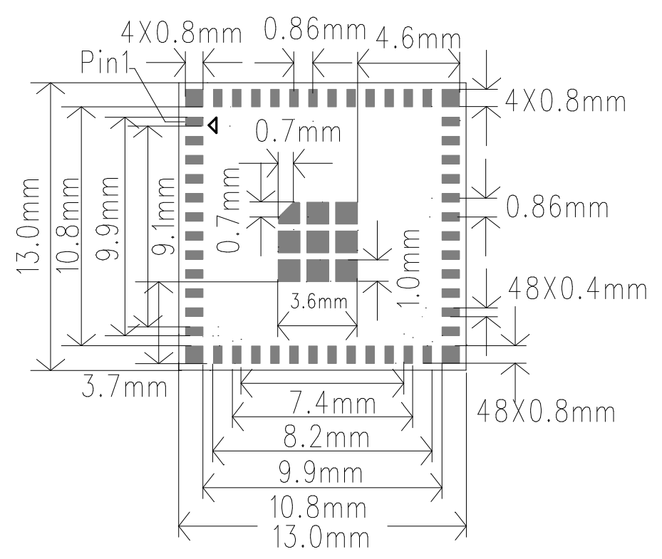
5.2 Product Dimensions
13±0.1mm(L)X13±0.1mm(W)X0.8±0.1mm(H)
5.3 Module Package Diagram

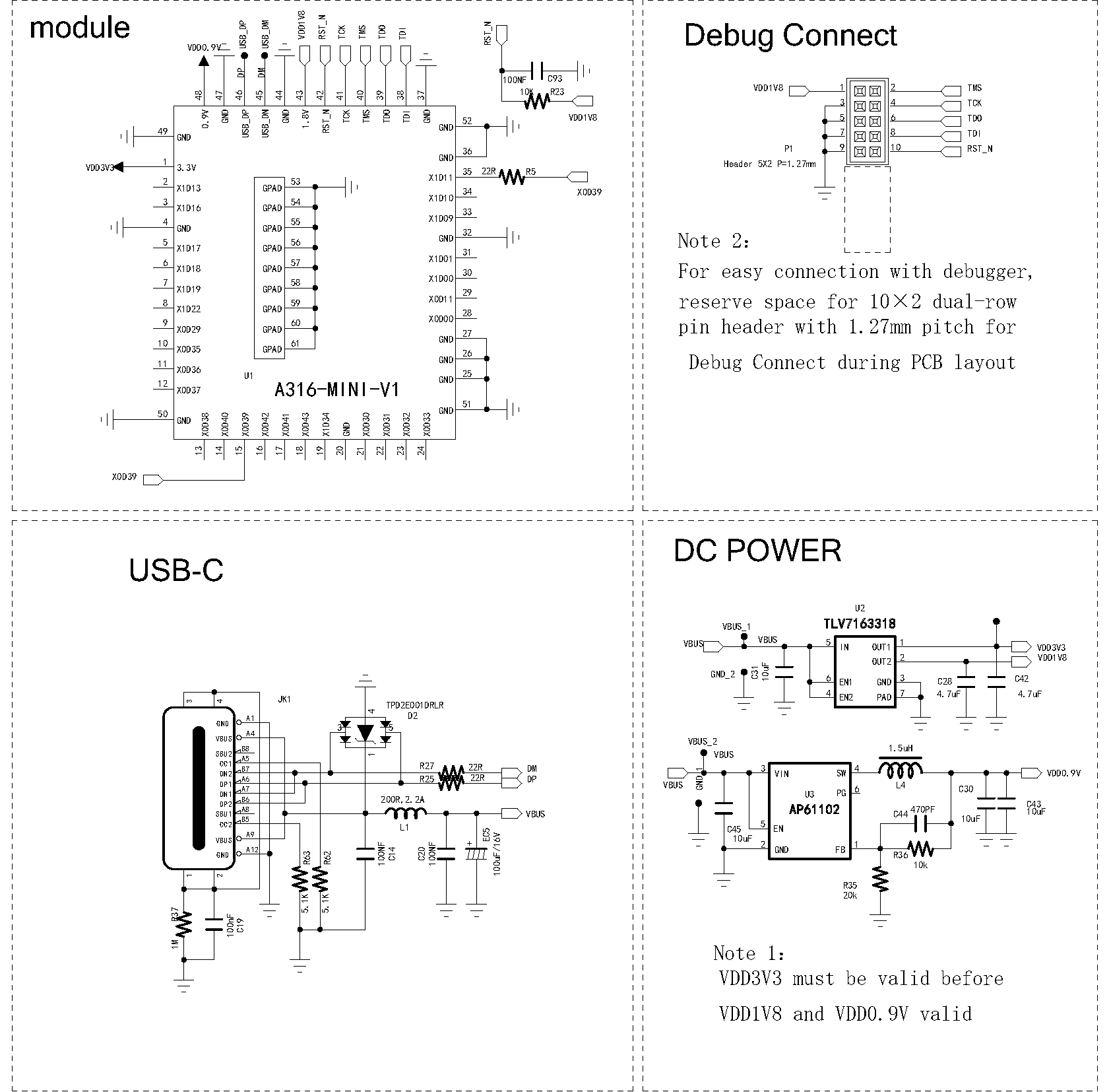
6. Minimal System Reference Design

7. Product Packaging Information
Tray + Outer Box Packaging
8. Revision History
| Version | Date | Description | Revised By |
|---|---|---|---|
| V1.0 | 2025-01-15 | Initial version release | |

