GM67211_VC1
48KHz Low-Latency Virtual 7.1 Gaming Audio Processor with Integrated EQ/FPS Enhancement and I²S Input Interface
1. Introduction
1.1 Product Description
GM67211 is a high-performance audio processor specifically developed for the PS5/SWITCH gaming market, supporting PCM 48KHz/16bit format to provide immersive audio experiences for gamers. This product is based on the XMOS high-performance chip and optimized specifically for gaming audio processing.
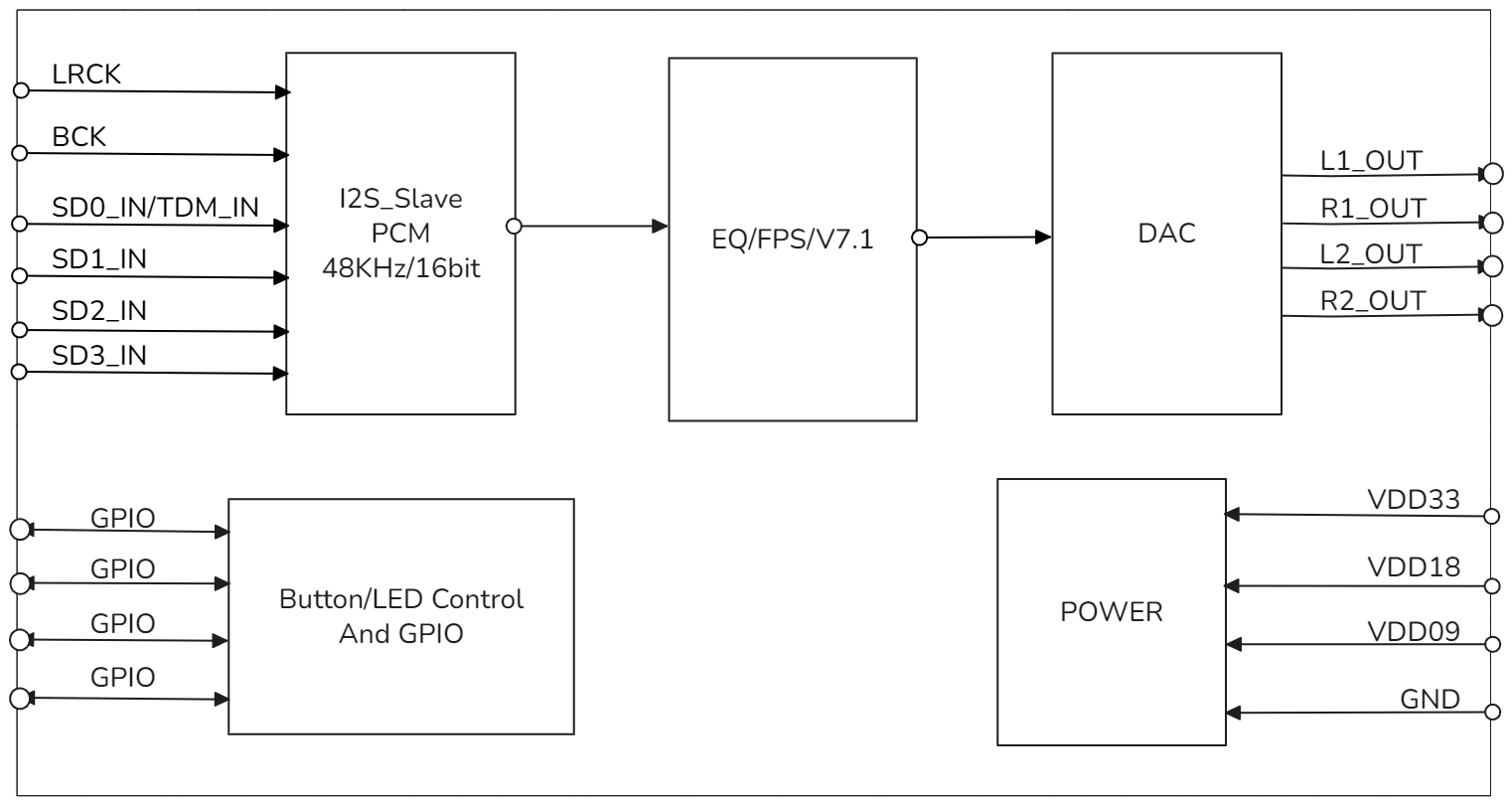
- GM67211 supports I²S digital audio input interface, processes the signal through a built-in SA Virtual 7.1 algorithm, and outputs high-quality 2-channel analog audio signals to meet gaming audio playback requirements.
- GM67211 integrates the SA Virtual 7.1 algorithm, which synthesizes 7.1 channels into 2-channel analog output through an algorithm optimized for human hearing, allowing users to experience full surround sound effects and audio positioning through headphones.
- The product adopts a standard I²S interface design with excellent compatibility, enabling it to work with various HDMI Repeaters.
1.2 Product Features
Gaming Audio Enhancement Features
- FPS Game Enhancement Mode
- Optimized specifically for first-person shooter games
- Provides more precise spatial directionality
- Enhances critical sound effects such as footsteps and gunshots
- Improves competitive gaming performance
- SA Virtual 7.1 Algorithm
- Converts 7.1 channels to 2-channel output through specialized algorithms
- Optimized for human hearing to provide 360-degree full surround sound and audio positioning effects
Audio Performance Features
- Supports 48kHz/16bit PCM format, optimized for gaming scenarios
- Low-latency audio processing ensures smooth gaming experience
Interface Support Features
- Multiple Digital Interface Support
- Supports I²S slave mode audio input
1.3 Application Scenarios
- PS5 HDMI Virtual 7.1 Gaming Sound Card

- Switch HDMI Virtual 7.1 Gaming Sound Card

- Switch Type-C Dock with Integrated Virtual 7.1 Gaming Sound Card

1.4 Product Functional Block Diagram

1.5 Ordering Information
| PRODUCT | ORDERING NUMBER | PACKAGE BODY | SIZE (NOM) | Comments |
|---|---|---|---|---|
| GM67211_VC1 | GM67211-VC1 | SMT LGA-52 | 13x13mm | 48KHz Low-Latency Virtual 7.1 Gaming Audio Processor with Integrated EQ/FPS Enhancement and I²S Input Interface |
2. Modes and Performance Specifications
2.1 Supported Function Modes
When the mode switch button is pressed once, the system cycles through three audio effect modes, switching to the next mode with each press.
| Mode Number | Audio Effect Mode | Function Description |
|---|---|---|
| 1 | No Audio Effect Mode | Audio signal passes through without any audio effect processing, maintaining original audio output |
| 2 | FPS/EQ Mode | Enables FPS gaming enhancement algorithm, enhances critical sound effects such as footsteps and gunshots, improves spatial directionality |
| 3 | Virtual 7.1 Mode | Enables SA Virtual 7.1 algorithm, converts 7.1 channel audio to 2-channel output, provides 360-degree full surround sound and audio positioning effects |
2.2 Supported Audio Formats and Sample Rates:
| Audio Format | Supported Sample Rates | Bit Depth |
|---|---|---|
| PCM | 48kHz | 16bit |
3. Pin Configuration and Functions
3.1 GM67211_VC1 Pin Layout

3.2 GM67211_VC1 Pin Description
| Pin Number | Name | Type | Function |
|---|---|---|---|
| 1 | 3.3V | P | 3.3V Supply |
| 2 | X1D13 | I | S/PDIF OUT |
| 3 | X1D16 | I | I2S_D3IN, Connect to HDMI I2S D3OUT |
| 4 | GND | P | GND |
| 5 | X1D17 | I | I2S_D2IN, Connect to HDMI I2S D2OUT |
| 6 | X1D18 | I/O | I2S_D1IN, Connect to HDMI I2S D1OUT |
| 7 | X1D19 | I/O | I2S_D0IN, Connect to HDMI I2S D0OUT |
| 8 | X1D22 | I | nc |
| 9 | X0D29 | I | NC |
| 10 | X0D35 | I/O | NC |
| 11 | X0D36 | I/O | NC |
| 12 | X0D37 | I/O | I2C_SCL Connect to TLV320AIC3204 I2C_SCL |
| 13 | X0D38 | I/O | I2C_SDA Connect to TLV320AIC3204 I2C_SDA |
| 14 | X0D40 | O | NC |
| 15 | X0D39 | I/O | DFU pin,Active High |
| 16 | X0D42 | I/O | NC |
| 17 | X0D41 | I/O | CTRL_MUTE, Active High |
| 18 | X0D43 | I/O | NC |
| 19 | X1D34 | O | NC |
| 20 | GND | P | GND |
| 21 | X0D30 | I | NC |
| 22 | X0D31 | I | NC |
| 23 | X0D32 | I | NC |
| 24 | X0D33 | I | NC |
| 25 | GND | P | GND |
| 26 | GND | P | GND |
| 27 | GND | P | GND |
| 28 | X0D00 | I/O | NC |
| 29 | X0D11 | I | MCLK_IN Connect to LV320AIC3204 MCLK and HDMI MCLK |
| 30 | X1D00 | I | NC |
| 31 | X1D01 | O | I2S_LRCK, Connect to TLV320AIC3204 I2S LRCK and HDMI I2S LRCK |
| 32 | GND | P | GND |
| 33 | X1D09 | I/O | I2S_DOUT,Connect to TLV320AIC3204 |
| 34 | X1D10 | O | I2S_BCLK, Connect to TLV320AIC3204 I2S BCLK and HDMI I2S BCLK |
| 35 | X1D11 | O | MCLK_IN Connect to LV320AIC3204 MCLK and HDMI MCLK |
| 36 | GND | P | GND |
| 37 | GND | P | GND |
| 38 | TDI | I/O | XTAGDEBUG PIN |
| 39 | TDO | I/O | XTAGDEBUG PIN |
| 40 | TMS | I/O | XTAGDEBUG PIN |
| 41 | TCK | I/O | XTAGDEBUG PIN |
| 42 | RST_N | I/O | REST, Active low |
| 43 | 1.8V | P | 1.8V Supply |
| 44 | GND | P | GND |
| 45 | USB_DM | I/O | USB_DM |
| 46 | USB_DP | I/O | USB_DP |
| 47 | GND | P | GND |
| 48 | 0.9V | P | 0.9V Supply |
| 49 | GND | P | GND |
| 50 | GND | P | GND |
| 51 | GND | P | GND |
| 52 | GND | P | GND |
Pin Type Definitions
I/O type definitions in the table: I=Input, O=Output, P=Power, I/O=Input/Output
4. Hardware Specifications
4.1 Normal Operating Conditions
| Function | Minimum | Typical | Maximum | Unit |
|---|---|---|---|---|
| Operating Temperature | 0 | - | 70 | ℃ |
| 3.3V Operating Voltage | 3.0 | 3.3 | 3.6 | V |
| 1.8V Operating Voltage | 1.62 | 1.80 | 1.98 | V |
| 0.9V Operating Voltage | 0.855 | 0.90 | 0.945 | V |
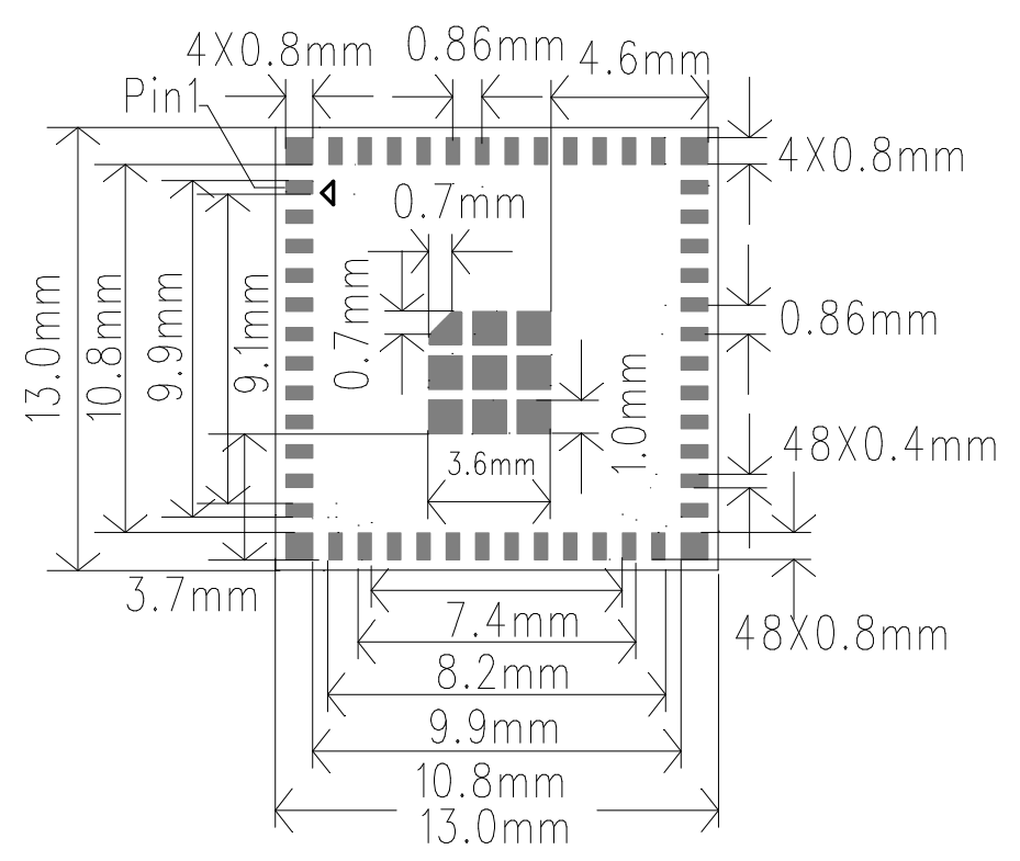
4.2 Product Dimensions
13±0.1mm(L)X13±0.1mm(W)X0.8±0.1mm(H)
4.3 Module Package Diagram

5 Product Packaging Information
Tray + Outer Box Packaging
6. Revision History
| Version | Date | Description | Revised By |
|---|---|---|---|
| V1.0 | 2025-08-23 | Initial release | |
| V1.1 | 2025-09-10 | Modified pin definitions | |

